
Understanding the standardized color schemes within LAN cabling is crucial for reliable network performance․ These schemes, often detailed in PDF guides, ensure consistent wiring
and simplify troubleshooting efforts for network administrators and technicians․
The Importance of Standardized Wiring
Consistent and standardized wiring practices, meticulously documented in resources like a LAN cable color coding PDF, are paramount for establishing dependable network connectivity․ Deviations from these standards introduce potential points of failure, making troubleshooting exponentially more complex and time-consuming․ Proper color coding ensures that each wire corresponds to a specific function – transmitting or receiving data – within the cable․
Without standardization, identifying wiring errors becomes a laborious process of trial and error․ A readily available PDF guide detailing the correct color sequences streamlines installation and repair, minimizing downtime and maximizing network efficiency․ Furthermore, standardized wiring facilitates collaboration among technicians, ensuring that anyone working on the network can quickly understand and maintain the cabling infrastructure․ This reduces the risk of misconfigurations and enhances overall network reliability․
TIA/EIA-568 Standards Overview
The Telecommunications Industry Association (TIA) and the Electronic Industries Alliance (EIA) jointly developed the TIA/EIA-568 standards, which govern structured cabling systems, including detailed specifications for LAN cable color coding – often found in comprehensive PDF documents․ These standards define two primary wiring schemes: T568A and T568B․
These standards aren’t merely suggestions; they are industry benchmarks ensuring interoperability and performance․ A TIA/EIA-568 PDF will illustrate the precise wire arrangements for each scheme, detailing which color corresponds to each pin on the RJ45 connector․ Adherence to these standards guarantees compatibility with a wide range of networking devices and minimizes signal interference․ Understanding these standards is fundamental for anyone involved in network installation, maintenance, or troubleshooting, as they provide a clear framework for consistent and reliable cabling․

Understanding LAN Cable Types
Different LAN cable categories (Cat5e, Cat6, Cat6a, Cat7) support varying bandwidths and speeds; color coding remains consistent across these types, as detailed in PDF guides․
Cat5e Cables: Common Uses and Limitations
Cat5e cables are widely utilized for home and office networks, supporting Gigabit Ethernet speeds up to 1000 Mbps over shorter distances․ They remain a cost-effective solution for many standard networking applications, including connecting computers, routers, and switches․ However, Cat5e cables have limitations regarding bandwidth and susceptibility to interference compared to newer standards․
Crucially, proper wiring, guided by color coding schemes detailed in readily available PDF resources, is essential for achieving optimal performance with Cat5e․ Incorrect wiring can significantly degrade signal quality and lead to connectivity issues․ While sufficient for many tasks, Cat5e may struggle with bandwidth-intensive applications like 4K video streaming or large file transfers, especially over longer cable runs․ For these scenarios, upgrading to Cat6 or higher is recommended․
Cat6 Cables: Enhanced Performance and Shielding
Cat6 cables represent a significant improvement over Cat5e, offering increased bandwidth capabilities – up to 10 Gigabit Ethernet at distances up to 55 meters, and Gigabit Ethernet up to 100 meters․ This enhanced performance is achieved through tighter twists in the wire pairs and improved shielding options, reducing crosstalk and interference․ Shielding comes in various forms, including UTP (Unshielded Twisted Pair), STP (Shielded Twisted Pair), and FTP (Foiled Twisted Pair)․
Accurate color coding, as illustrated in numerous PDF guides, is paramount when terminating Cat6 cables to maintain their superior performance․ Incorrect wiring negates the benefits of the enhanced specifications․ Cat6 is ideal for demanding network environments, supporting high-bandwidth applications like streaming, gaming, and data centers․ While more expensive than Cat5e, the investment provides future-proofing and improved reliability․
Cat6a and Cat7 Cables: For High-Bandwidth Applications
Cat6a and Cat7 cables are designed for the most demanding networking needs, supporting 10 Gigabit Ethernet over longer distances (up to 100 meters for Cat6a) and even 40/100 Gigabit Ethernet with Cat7․ These cables feature even more robust shielding than Cat6, significantly reducing alien crosstalk and electromagnetic interference․ Cat7 utilizes a GG45 connector, differing from the RJ45 used in Cat6a and earlier standards․
Maintaining precise color coding, detailed in readily available PDF resources, is absolutely critical when working with these high-performance cables․ The tighter specifications and shielding require meticulous termination to realize their full potential․ These cables are commonly found in data centers, server rooms, and other environments where extremely high bandwidth and data integrity are essential․ While more costly, they provide a future-proof solution for evolving network demands․

Color Codes for T568A Wiring
T568A employs a specific wire color sequence, often detailed in PDF guides, for consistent network connectivity․ This standard ensures proper signal transmission and reliable data flow․
T568A Pinout Diagram Explained
The T568A pinout diagram, frequently found in comprehensive LAN cable PDF resources, illustrates the precise arrangement of individual wire colors within an RJ45 connector․ This diagram is fundamental for creating reliable Ethernet connections․ It details which color-coded wire corresponds to each of the eight pins on the connector – positions 1 through 8․
Typically, the diagram will visually represent the connector’s face, clearly labeling each pin․ The color sequence begins with Green/White (pin 1), followed by Green (pin 2), Orange/White (pin 3), Blue (pin 4), Blue/White (pin 5), Orange (pin 6), Brown/White (pin 7), and finally Brown (pin 8)․ Understanding this layout, as presented in a PDF guide, is essential for successful cable termination and network functionality․ Incorrect wiring leads to connectivity issues․
Wire Color Sequence in T568A
The T568A standard dictates a specific wire color sequence, meticulously detailed in LAN cable PDF documentation․ This sequence is critical for maintaining signal integrity and ensuring proper network communication․ Starting from the leftmost pin when facing the connector’s clip side, the order is: Green/White, Green, Orange/White, Blue, Blue/White, Orange, Brown/White, and Brown․
PDF guides often visually emphasize this order, sometimes using color-coded illustrations for clarity․ Adhering to this precise sequence is paramount; deviations can result in non-functional connections or intermittent network performance․ The pairing of solid and striped wires (e․g․, Green and Green/White) is also important, as it contributes to reducing crosstalk and interference․ Consistent application of this sequence, as shown in a reliable PDF, guarantees a stable and efficient network․
Applications Where T568A is Preferred
While both T568A and T568B are widely used, T568A finds preference in specific networking scenarios, often detailed within comprehensive LAN cable PDF resources․ Historically, it was favored by some early networking equipment manufacturers, leading to its continued use in maintaining compatibility with legacy systems․
PDF guides highlight its suitability for installations where uniformity is key, particularly in larger networks where a single wiring standard simplifies troubleshooting and maintenance․ Some technicians prefer T568A due to its perceived advantages in reducing crosstalk in certain cable types․ It’s commonly employed in environments requiring strict adherence to specific standards or when interconnecting devices from different vendors․ Choosing T568A, as outlined in a detailed PDF, ensures a consistent and reliable network infrastructure․

Color Codes for T568B Wiring
T568B utilizes a different wire sequence than T568A, commonly detailed in LAN cable PDF guides․ This standard is prevalent in North America and simplifies
patch cable creation․
T568B Pinout Diagram Explained
The T568B pinout diagram, frequently found within comprehensive LAN cable PDF resources, illustrates the precise arrangement of individual wire colors within an RJ45 connector․ This standard dictates which color corresponds to each of the eight pins, ensuring proper signal transmission․ Pin 1 is typically orange/white, followed by orange, green/white, blue, blue/white, green, brown/white, and finally brown on Pin 8․
Understanding this diagram is paramount for creating functional Ethernet cables․ Incorrect wiring leads to connectivity issues or complete network failure․ Many PDF guides offer visual representations alongside detailed explanations, making it easier to follow the sequence․ The diagram clearly shows how to arrange the wires to maintain the correct pairing for optimal performance, minimizing crosstalk and maximizing data throughput․ Consistent adherence to the T568B standard is vital for interoperability between network devices․
Wire Color Sequence in T568B
The T568B wiring scheme, detailed in numerous LAN cable PDF guides, follows a specific color order: orange/white, orange, green/white, blue, blue/white, green, brown/white, and brown․ This sequence is crucial for maintaining signal integrity and ensuring proper network communication․ PDF resources often highlight this order with clear diagrams and tables for easy reference during cable termination․
It’s important to note that this sequence differs from T568A, and mixing the two standards will result in a non-functional cable․ The consistent application of the T568B color code minimizes signal interference and maximizes data transfer speeds․ Many technicians rely on color-coded wiring diagrams found in PDF format to quickly and accurately terminate cables, reducing errors and improving network reliability․ Following the sequence precisely is key to a successful connection․
Applications Where T568B is Preferred
T568B is widely favored in North America, as detailed in many LAN cable PDF guides, due to its historical prevalence and compatibility with existing infrastructure․ It’s commonly used in commercial buildings, homes, and offices for connecting computers, routers, and switches․ PDF documentation often emphasizes its suitability for general networking applications where backward compatibility is essential․
While both T568A and T568B function effectively, T568B’s popularity means it’s often the default standard assumed in many installations․ Technicians frequently consult PDF resources to confirm T568B is the appropriate choice for specific projects․ It’s particularly useful when connecting to older network devices or when maintaining consistency across an existing network․ Choosing T568B simplifies troubleshooting and ensures interoperability within established network environments, as outlined in comprehensive cabling PDFs․
Straight-Through vs․ Crossover Cables
PDF guides clarify that straight-through cables use identical wiring on both ends, while crossover cables swap transmit and receive wires for direct device connection․
When to Use a Straight-Through Cable
Straight-through cables, as detailed in numerous LAN cable color coding PDF resources, are the most commonly used type of Ethernet cable․ They are primarily employed for connecting dissimilar devices – meaning a computer to a switch, or a switch to a router․ This is because these devices typically have different internal wiring configurations, and the straight-through cable maintains the correct pin assignments for proper communication․
PDF guides emphasize that when connecting a computer directly to a hub or switch, or linking a router to a switch, a straight-through cable is the appropriate choice․ They are also standard for connecting network printers and other peripherals to the network infrastructure․ Essentially, if the devices at each end of the connection aren’t the same type, a straight-through cable is almost always the correct solution, ensuring seamless data transfer and network functionality․
When to Use a Crossover Cable (Historical Context)
Crossover cables, once essential, are now largely obsolete due to advancements in networking technology․ LAN cable color coding PDF documentation historically detailed their use for directly connecting two identical devices – such as computer-to-computer, switch-to-switch, or router-to-router․ This was necessary because older devices transmitted and received signals on the same pins, requiring a reversed wiring configuration on one end․
PDF guides from the early 2000s would extensively cover crossover cable construction․ However, the introduction of Auto-MDIX (Automatic Medium Dependent Interface Crossover) in most modern network devices has eliminated the need for them․ Auto-MDIX automatically detects the cable type and adjusts the port configuration accordingly․ Consequently, crossover cables are rarely required today, representing a significant shift in networking practices as outlined in updated cabling PDFs․
Auto-MDIX and its Impact on Cable Requirements
Auto-MDIX revolutionized LAN cabling, significantly simplifying network setup and reducing the need for specialized cables․ Modern network devices equipped with Auto-MDIX automatically detect the connected cable type – straight-through or crossover – and configure the interface accordingly․ This eliminates the guesswork previously required when connecting network devices, as detailed in older LAN cable color coding PDF guides․
Consequently, the vast majority of current network installations utilize standard straight-through cables exclusively․ PDF documentation now focuses primarily on straight-through wiring schemes (T568A or T568B), as crossover cables are rarely necessary․ Auto-MDIX effectively renders crossover cables obsolete in most scenarios, streamlining cabling practices and reducing potential compatibility issues․ This advancement is a key takeaway from contemporary network cabling PDFs, emphasizing simplicity and standardization․

Tools for LAN Cable Termination
Proper tools, detailed in cabling PDFs, are essential for successful LAN cable termination․ These include cable strippers, crimping tools, and testers, ensuring secure and reliable connections․
Cable Strippers: Choosing the Right Tool
Selecting the appropriate cable stripper is paramount for clean and precise cable preparation, often illustrated in comprehensive LAN cabling PDFs․ Different cable types – Cat5e, Cat6, and beyond – require varying degrees of jacket removal without damaging the delicate inner wires․
Rotary blade strippers offer versatility, accommodating a range of cable diameters with adjustable settings․ However, for high-volume work, automatic cable strippers can significantly increase efficiency․ Ensure the stripper’s blade is sharp to prevent nicking or cutting the conductors, which can compromise signal integrity․
Consider strippers specifically designed for shielded cables (STP) if your network utilizes them, as these tools often include a provision for carefully removing the shielding without damaging the twisted pairs․ Always consult a color coding PDF to understand wire gauge requirements and avoid over-stripping․
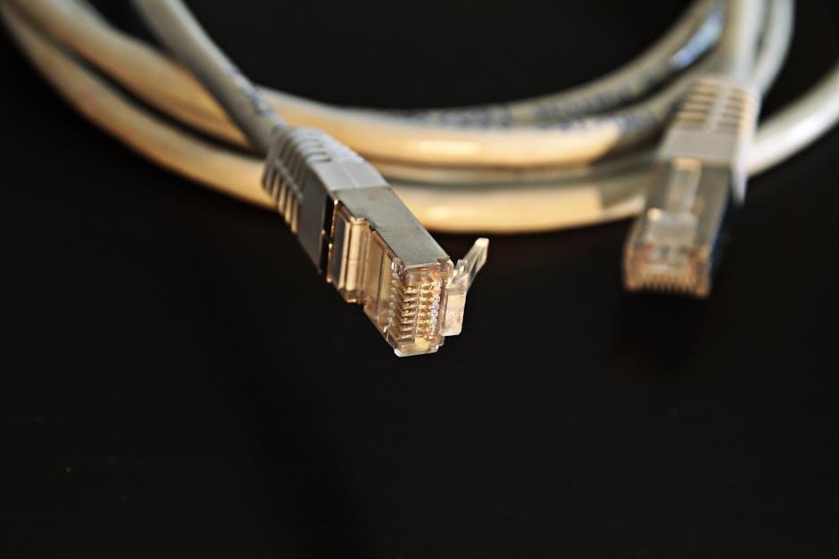
Crimping Tools: Ensuring a Secure Connection
A reliable crimping tool is essential for terminating RJ45 connectors onto LAN cables, a process frequently detailed in color coding PDF guides․ The tool must firmly seat the connector pins into the conductors, establishing a solid electrical connection․
Ratchet crimping tools are highly recommended, as they require full compression before releasing, preventing incomplete crimps․ Different connectors (Cat5e, Cat6, etc․) may necessitate specific die sets within the crimping tool; verify compatibility before use․
Inspect crimped connectors closely for proper pin insertion and secure cable retention; A poorly crimped connection can lead to intermittent connectivity or complete signal loss․ Referencing a color coding PDF alongside the crimping process ensures correct wire placement and a robust, lasting connection․
Cable Testers: Verifying Cable Integrity
Post-termination, cable testers are indispensable for confirming the integrity of your LAN cable runs, complementing the guidance found in color coding PDF resources․ These devices verify proper wire map, continuity, and the absence of shorts or opens․
Basic cable testers check for wire pairing correctness, while advanced models measure cable length, signal strength, and NEXT (Near-End Crosstalk) performance․ Utilizing a tester minimizes troubleshooting time and ensures optimal network performance․
Always compare the tester’s results against the expected wiring scheme (T568A or T568B), often visually represented in color coding PDFs․ Identifying and correcting wiring errors before connecting to network devices prevents potential connectivity issues and data loss, guaranteeing a stable network․
Troubleshooting Common LAN Cable Issues
Identifying problems requires understanding correct wiring, detailed in color coding PDF guides․ Cable testers pinpoint faults like shorts or opens, ensuring reliable connections․
Identifying Wiring Errors with a Cable Tester
Utilizing a cable tester is paramount when diagnosing LAN connectivity issues․ These devices verify the integrity of each wire pair, confirming adherence to either T568A or T568B standards – details readily available in color coding PDF documentation․ A tester sends signals through each wire and confirms their arrival at the other end in the correct sequence․
Common errors detected include crossed wires, open circuits (broken wires), short circuits (wires touching), and split pairs․ The tester’s display will typically indicate which wires are faulty, allowing for precise identification and correction․ Many advanced testers can also measure cable length and signal strength, providing a comprehensive assessment of cable quality․ Referencing a color coding PDF alongside the tester’s results streamlines the troubleshooting process, ensuring accurate repairs and optimal network performance․
Dealing with Signal Loss and Interference
Signal loss and interference significantly degrade network performance․ Proper cable selection, adhering to color coding standards detailed in available PDF guides, is a crucial first step․ Shielded Twisted Pair (STP) cabling offers superior protection against electromagnetic interference (EMI) and radio frequency interference (RFI) compared to Unshielded Twisted Pair (UTP)․
Furthermore, maintaining cable bends within specified radii prevents damage to the conductors, minimizing signal attenuation․ Avoid running LAN cables parallel to power cables or fluorescent lights, as these are common sources of interference․ Ensure proper grounding of STP cables to effectively dissipate unwanted noise․ Regularly inspect connectors for corrosion or damage, as these can also contribute to signal degradation․ Consulting a color coding PDF confirms correct termination, vital for optimal signal transmission․
Recognizing Damaged Cables and Connectors
Identifying physical damage is paramount for network stability․ Inspect cables for cuts, kinks, or crushing, which compromise internal wiring and signal integrity․ A color coding PDF can assist in verifying correct re-termination if damage necessitates repair․ Connectors should be examined for bent or broken pins, loose housings, or signs of corrosion – all indicators of potential failure․
Furthermore, look for strain relief issues where the cable enters the connector; this area is prone to breakage․ A cable tester, referenced in many PDF guides, can pinpoint intermittent connections or shorts caused by damaged conductors․ Discard any cable or connector exhibiting significant physical damage; attempting to use compromised components introduces instability and potential security vulnerabilities․ Proper handling and careful inspection are key preventative measures․

Advanced LAN Cabling Concepts
Exploring specialized cabling like STP and plenum-rated options requires understanding their unique applications․ Color coding PDFs detail these nuances, aiding in proper installation and compliance․
Shielded Twisted Pair (STP) Cabling
Shielded Twisted Pair (STP) cabling incorporates an additional layer of protection against electromagnetic interference (EMI) and radio-frequency interference (RFI)․ This shielding, typically a foil or braided mesh, significantly improves signal integrity, especially in environments with high electrical noise․ Color coding standards, readily available in comprehensive PDF guides, extend to STP cables, often utilizing a distinct color for the shield drain wire․
Proper grounding of the STP shield is paramount for its effectiveness․ These PDFs emphasize the importance of connecting the shield drain wire to a proper grounding point to dissipate interference․ Different STP categories (like Cat5e STP, Cat6 STP) have specific color coding conventions detailed within these resources․ Understanding these nuances is vital for installers to ensure optimal performance and avoid signal degradation․ Incorrectly terminated STP cabling can actually increase interference, negating its benefits․
Plenum-Rated Cabling for Air Handling Spaces
Plenum spaces – areas used for air circulation in buildings – require specialized cabling to mitigate fire hazards․ Plenum-rated cables possess a flame-retardant outer jacket that limits smoke and toxic fumes when exposed to heat or flame․ While color coding itself doesn’t fundamentally change for plenum-rated cables, detailed PDF guides often highlight the importance of verifying the “CMP” (Communications Media Plenum) rating on the cable jacket․
These PDFs emphasize that standard PVC-jacketed cables are not permitted in plenum spaces due to their hazardous combustion byproducts․ The color coding schemes (T568A/B) remain consistent, but installers must prioritize using cables specifically certified for plenum environments․ Identifying plenum-rated cables often involves looking for specific markings and verifying compliance with building codes․ Ignoring this requirement can lead to significant safety risks and code violations, as outlined in many cabling installation PDFs․
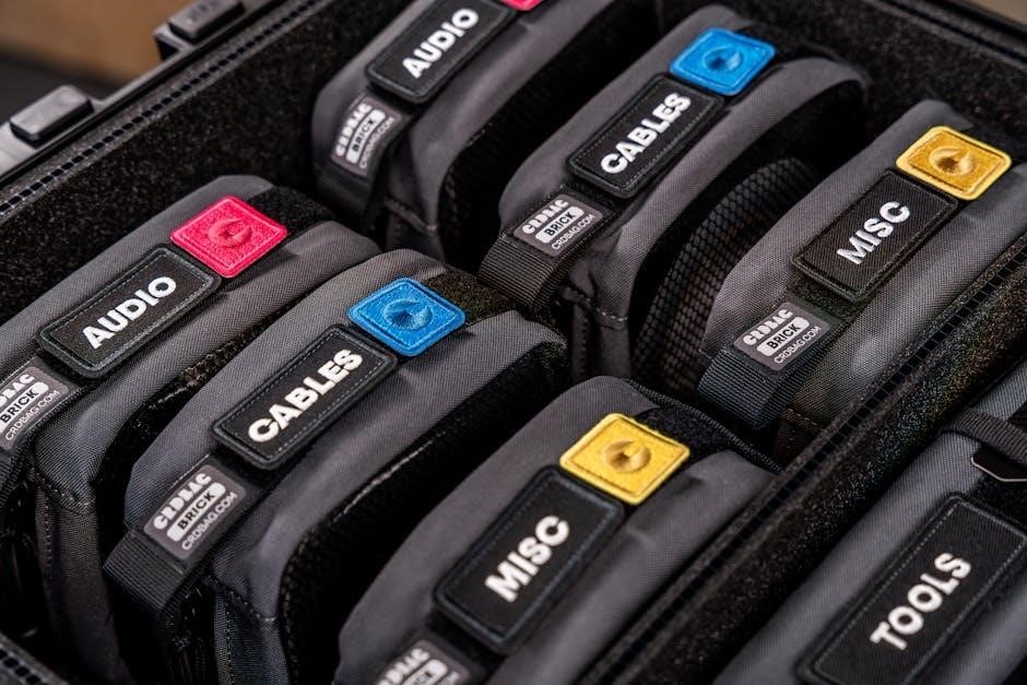
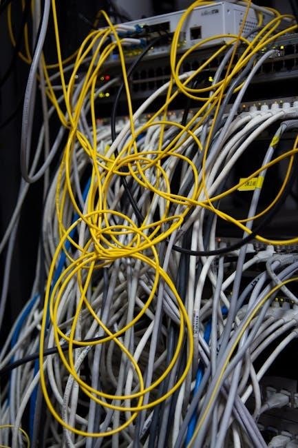
Cable Management Best Practices
Effective cable management is vital for maintaining network reliability and simplifying future troubleshooting․ While PDF guides on LAN cable color coding primarily focus on wiring schemes, they often briefly touch upon best practices for organization․ Proper cable routing, bundling, and labeling significantly reduce the risk of accidental disconnections or damage․
Many comprehensive cabling PDFs recommend using color-coded cable ties or labels to further differentiate cable runs, even beyond the standard wire color coding․ This is particularly useful in complex installations․ Maintaining adequate bend radius, avoiding tight turns, and securing cables with appropriate hardware are also crucial․ Good cable management improves airflow, prevents overheating, and makes it easier to trace cables when identifying issues – a point frequently emphasized in detailed installation PDFs․ Consistent practices contribute to a more maintainable and scalable network infrastructure․
Be First to Comment